Mo-Sys StarTracker: Difference between revisions
m (Wodie moved page Mo-Sys Star Tracker to Mo-Sys StarTracker without leaving a redirect) |
mNo edit summary |
||
| Line 1: | Line 1: | ||
= | = Unofficial users manual = | ||
This manual was created as result of my experience with a brand new StarTracker and the frustration trying to understand what I was doing and not just blindly follow instructions blindly, plus finding a lot of settings and features are not explained on the manual and no answer received from the manufacturer. Seems they want the product to be a mystery for users and owners and solve their problems by themselves. | |||
= | == Stars placement == | ||
Stars should be placed in at least two different levels. | |||
Distance between stars should be 1/10 of the stars height. | |||
= Data = | == Initial calibration == | ||
Tools needed: | |||
# Measuring tape. | |||
# Laser measuring device. | |||
# Gaffer tape. | |||
For best practice, designate a startup calibration area, it could be at any part of your studio where the StarTracker can see stars. It is advised to build a calibration rig as the one built in the picture. | |||
[[File:mosys_calibration_rig.jpeg|none|800x600]] | |||
= Menus and functions description = | |||
== Main == | |||
== Alg == | |||
== Calib == | |||
== Mapping == | |||
== Data == | |||
=== Output === | |||
* Sync Type - Select your GenLock Input signal, Black Burst, TriSync and SDI are accepted, but in SD format, HD is NOT SUPPORTED. | * Sync Type - Select your GenLock Input signal, Black Burst, TriSync and SDI are accepted, but in SD format, HD is NOT SUPPORTED. | ||
| Line 42: | Line 69: | ||
[[File:data_output.jpeg|none|800x600]] | [[File:data_output.jpeg|none|800x600]] | ||
== Input == | === Input === | ||
* Via Serial Lens - Select the input mode for lens data (Focus & Zoom). | * Via Serial Lens - Select the input mode for lens data (Focus & Zoom). | ||
| Line 69: | Line 96: | ||
[[File:data_input.jpeg|none|800x600]] | [[File:data_input.jpeg|none|800x600]] | ||
== Record == | === Record === | ||
* Jam - | * Jam - | ||
| Line 95: | Line 122: | ||
[[File:data_record.jpeg|none|800x600]] | [[File:data_record.jpeg|none|800x600]] | ||
== Lens Data == | === Lens Data === | ||
* Enable - Turn On if using DigiLens. | * Enable - Turn On if using DigiLens. | ||
| Line 112: | Line 140: | ||
[[File:data_lensdata.jpeg|none|800x600]] | [[File:data_lensdata.jpeg|none|800x600]] | ||
== Network == | === Network === | ||
Please reboot after any changes on this menu. | Please reboot after any changes on this menu. | ||
| Line 138: | Line 166: | ||
[[File:data_network.jpeg|none|800x600]] | [[File:data_network.jpeg|none|800x600]] | ||
== Advanced == | === Advanced === | ||
* F4 Status - On to send data to D3. | * F4 Status - On to send data to D3. | ||
| Line 148: | Line 177: | ||
[[File:data_advanced.jpeg|none|800x600]] | [[File:data_advanced.jpeg|none|800x600]] | ||
= Tunning = | == Tunning == | ||
Revision as of 16:54, 26 March 2021
Unofficial users manual
This manual was created as result of my experience with a brand new StarTracker and the frustration trying to understand what I was doing and not just blindly follow instructions blindly, plus finding a lot of settings and features are not explained on the manual and no answer received from the manufacturer. Seems they want the product to be a mystery for users and owners and solve their problems by themselves.
Stars placement
Stars should be placed in at least two different levels. Distance between stars should be 1/10 of the stars height.
Initial calibration
Tools needed:
- Measuring tape.
- Laser measuring device.
- Gaffer tape.
For best practice, designate a startup calibration area, it could be at any part of your studio where the StarTracker can see stars. It is advised to build a calibration rig as the one built in the picture.
Menus and functions description
Main
Alg
Calib
Mapping
Data
Output
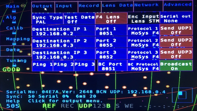
- Sync Type - Select your GenLock Input signal, Black Burst, TriSync and SDI are accepted, but in SD format, HD is NOT SUPPORTED.
- Test Data - Select diferent test patters of data set via network.
- F4 Lens - Turn On if using DigiLens, this option also shows in Lens Data sub menu.
- Encoder Lens Input only shows which lens encoder is selected on Input sub menu.
- Serial Out - Enables MoSys serial output if not using ethernet option.
Unicast
- Destination IP 1, 2, 3 - Set the input to send unicast UDP data.
- Port 1, 2, 3 - Selects the UDP port number.
- Protocol 1, 2, 3 - Select the protocol to be sent to each unicast address.
- Send UDP 1, 2, 3 - Enable/Disable the unicast data output.
- Ping 1, 2, 3 - send a ping to a Destination Address.
Broadcast
- BC Port - Selects the UDP broadcast port number.
- BC Protocol - Select the protocol to be sent to the broadcast address.
- Broadcast - Enable/Disable the broadcast data output.
Input
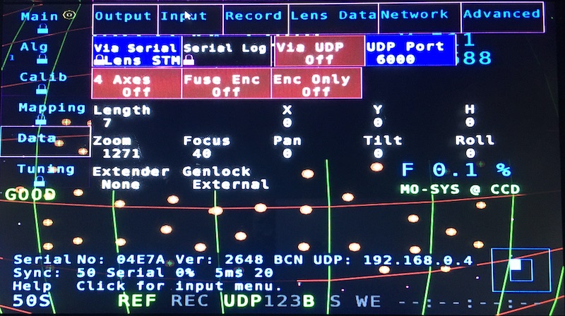
- Via Serial Lens - Select the input mode for lens data (Focus & Zoom).
- STM - External MoSys encoders.
- Serial Log - open a console log window.
- Via UDP - Enable/Disable UDP data input.
- UDP Port - Select the input UDP port.
- 4 Axes -
- Fuse Enc -
- Enc Only -
The screen also display information about
- External encoders X, Y, H, Pan, Tilt & Roll.
- Lens Focus & Zoom encoders.
- GenLock input signal type/status.
Record
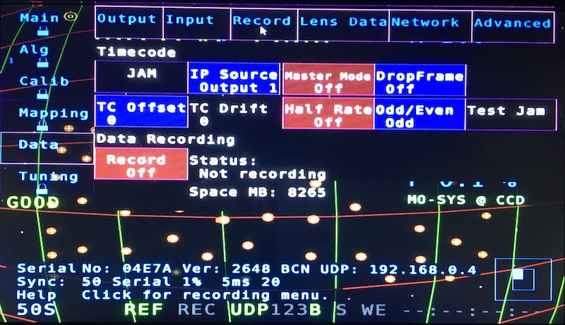
- Jam -
- IP Source Output -
- Master Mode -
- DropFrame -
- TC Offset -
- TC Drift - Display
- Half Rate -
- Odd/Even - Select the field for
- Test Jam -
- Record -
Status information display.
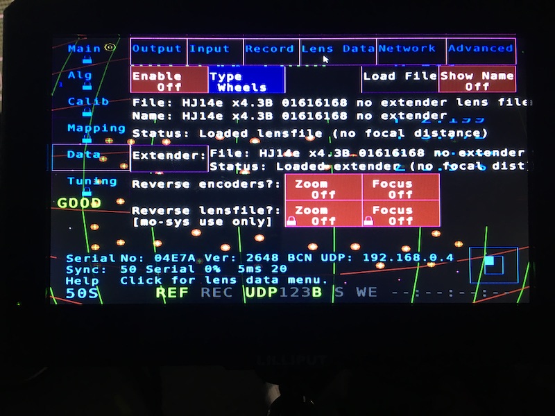
Lens Data
- Enable - Turn On if using DigiLens.
- Type - Select Wheels if using external encoders.
- Load File - Only apply for Digilens.
- Extender - Loads the Extender Menu.
- For external encoders, only set the extender X factor.
- Load Lens file only for DigiLens.
- Reverse Encoders - Invert the encoders direction for Focus or Zoom.
- Reverse Lens File - Invert the encoders direction for DigiLens Focus or Zoom.
Network
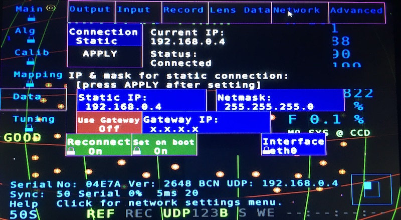
Please reboot after any changes on this menu.
- Connection - Set for Static or Dynamic IP.
- APPLY - Apply settings (you need to reboot unit).
- Static IP - This system IP address.
- Netmask - This system netmask.
- Use Gateway - Enable/Disable gateway address to talk to the Internet.
- Gateway IP - Gateway address for Internet conectivity.
- Reconect -
- Set on boot -
- Interface - Selects the interface to configure on this menu.
- eth0 is the Ethernet port.
- eth64 is the IP camera communications port.
Advanced
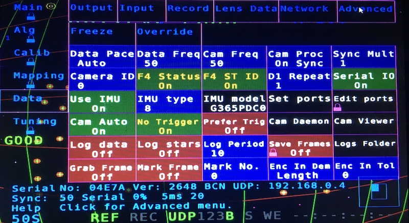
- F4 Status - On to send data to D3.
- F4 ST ID - On to be read properly on D3.
- Serial IO - Must be On for Gen Lock and Lens Encoders (reboot needed to apply changes).
- Use IMU - Need to be on, so IR camera works.
