Mo-Sys StarTracker: Difference between revisions
m (→Output) |
|||
| (8 intermediate revisions by the same user not shown) | |||
| Line 1: | Line 1: | ||
= | = Unofficial users manual = | ||
This manual was created as result of my experience with a brand new StarTracker. | |||
= | == Stars placement == | ||
Stars should be placed in at least two different levels. | |||
Distance between stars should be 1/10 of the stars height. | |||
= Data = | * Stars must be installed in a fixed and permanent structure. | ||
* Stars need to be placed as randomly as possible. | |||
* Stars must be placed in different heights (at least two levels). | |||
* Stars must be well separated, on an average 1/10th the distance from the floor to the ceiling height. | |||
* For stars size, see table 1. Stars shall not be closer than 1/15th of the height or 5x their diameters (whichever is greater). | |||
* Stars should be clearly visible (no objects, cables, etc hiding them). | |||
* In your higher sensor/camera height, you should have approximately 30 stars visible thru the camera, and never less than 11. | |||
StarTracker sensor have a 90 deg field of view. | |||
= Lens Encoders = | |||
You can use external lens bolt-on encoders or internal Digi lens. But never connect both at the same time. | |||
When using external lens encoders operate Zoom and Focus from one end stop to the other follwing start-up. | |||
Do zoom and Focus separately. This process will calibrate lens encoders range end stops. You will need to repeat after each power cycle. | |||
= Shortcuts | |||
You can enable/disable keyboard shortcuts under Main->Shortcuts. | |||
O Toggle on/off the optical sensor camera. | |||
S Save. | |||
R Reset/unload map. | |||
L Load | |||
A Refresh estimated star detection. | |||
Y Yes / confirm. | |||
N No / cancel. | |||
I Toggle on/off IMU (gyro). | |||
Esc Close current menu/cancel current operation. | |||
= Calibration guide = | |||
== set Exposure == | |||
Adjust the exposure using trial and error. | |||
Go to Alg menu, set the exposure level to 0.4 as a starting point. | |||
Visibility is adjusted in Alg>Star Vis set to normal. | |||
== Set radius == | |||
Star radius detection is set automatically, but you can make your own adjustments on Alg->Star Rad with values between 3 and 15. Nominal value is 5. | |||
== Initial calibration == | |||
Tools needed: | |||
# Measuring tape. | |||
# Laser measuring device. | |||
# Gaffer tape. | |||
For best practice, designate a startup calibration area, it could be at any part of your studio where the StarTracker can see stars. It is advised to build a calibration rig as the one built in the picture. | |||
[[File:mosys_calibration_rig.jpeg|none|800x600]] | |||
= Menus and functions description = | |||
== Main == | |||
== Alg == | |||
== Calib == | |||
== Mapping == | |||
== Data == | |||
=== Output === | |||
* Sync Type - Select your GenLock Input signal, Black Burst, TriSync and SDI are accepted, but in SD format, HD is NOT SUPPORTED. | * Sync Type - Select your GenLock Input signal, Black Burst, TriSync and SDI are accepted, but in SD format, HD is NOT SUPPORTED. | ||
| Line 42: | Line 119: | ||
[[File:data_output.jpeg|none|800x600]] | [[File:data_output.jpeg|none|800x600]] | ||
== Input == | === Input === | ||
* Via Serial Lens - Select the input mode for lens data (Focus & Zoom). | |||
:STM - External MoSys encoders. | |||
* Serial Log - open a console log window. | |||
* Via UDP - Enable/Disable UDP data input. | |||
* UDP Port - Select the input UDP port. | |||
* 4 Axes - | |||
* Fuse Enc - | |||
* Enc Only - | |||
The screen also display information about | |||
* External encoders X, Y, H, Pan, Tilt & Roll. | |||
* Lens Focus & Zoom encoders. | |||
* GenLock input signal type/status. | |||
[[File:data_input.jpeg|none|800x600]] | [[File:data_input.jpeg|none|800x600]] | ||
== Record == | === Record === | ||
* Jam - | |||
* IP Source Output - | |||
* Master Mode - | |||
* DropFrame - | |||
* TC Offset - | |||
* TC Drift - Display | |||
* Half Rate - | |||
* Odd/Even - Select the field for | |||
* Test Jam - | |||
* Record - | |||
Status information display. | |||
[[File:data_record.jpeg|none|800x600]] | [[File:data_record.jpeg|none|800x600]] | ||
== Lens Data == | === Lens Data === | ||
* Enable - Turn On if using DigiLens. | * Enable - Turn On if using DigiLens. | ||
| Line 65: | Line 190: | ||
[[File:data_lensdata.jpeg|none|800x600]] | [[File:data_lensdata.jpeg|none|800x600]] | ||
== Network == | === Network === | ||
Please reboot after any changes on this menu. | |||
* Connection - Set for Static or Dynamic IP. | |||
* APPLY - Apply settings (you need to reboot unit). | |||
* Static IP - This system IP address. | |||
* Netmask - This system netmask. | |||
* Use Gateway - Enable/Disable gateway address to talk to the Internet. | |||
* Gateway IP - Gateway address for Internet conectivity. | |||
* Reconect - | |||
* Set on boot - | |||
* Interface - Selects the interface to configure on this menu. | |||
:eth0 is the Ethernet port. | |||
:eth64 is the IP camera communications port. | |||
[[File:data_network.jpeg|none|800x600]] | [[File:data_network.jpeg|none|800x600]] | ||
== Advanced == | === Advanced === | ||
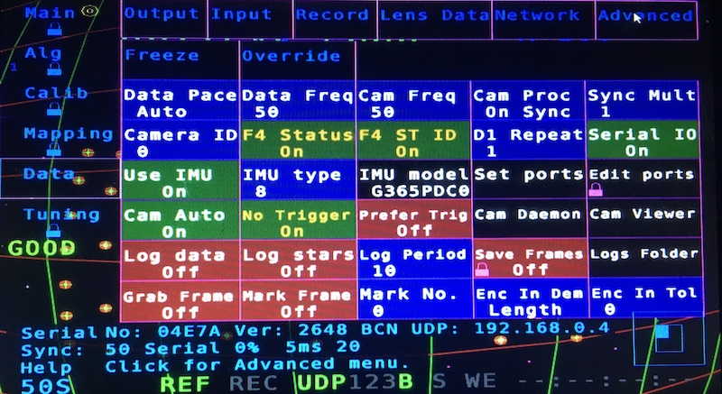
* F4 Status - On to send data to D3. | * F4 Status - On to send data to D3. | ||
* F4 ST ID - On to be read properly on D3. | * F4 ST ID - On to be read properly on D3. | ||
* Serial IO - Must be On for Gen Lock and Lens Encoders. | * Serial IO - Must be On for Gen Lock and Lens Encoders (reboot needed to apply changes). | ||
* Use IMU - Need to be on, so IR camera works. | * Use IMU - Need to be on, so IR camera works. | ||
[[File:data_advanced.jpeg|none|800x600]] | [[File:data_advanced.jpeg|none|800x600]] | ||
= Tunning = | == Tunning == | ||
Latest revision as of 21:15, 2 April 2021
Unofficial users manual
This manual was created as result of my experience with a brand new StarTracker.
Stars placement
Stars should be placed in at least two different levels. Distance between stars should be 1/10 of the stars height.
- Stars must be installed in a fixed and permanent structure.
- Stars need to be placed as randomly as possible.
- Stars must be placed in different heights (at least two levels).
- Stars must be well separated, on an average 1/10th the distance from the floor to the ceiling height.
- For stars size, see table 1. Stars shall not be closer than 1/15th of the height or 5x their diameters (whichever is greater).
- Stars should be clearly visible (no objects, cables, etc hiding them).
- In your higher sensor/camera height, you should have approximately 30 stars visible thru the camera, and never less than 11.
StarTracker sensor have a 90 deg field of view.
Lens Encoders
You can use external lens bolt-on encoders or internal Digi lens. But never connect both at the same time.
When using external lens encoders operate Zoom and Focus from one end stop to the other follwing start-up. Do zoom and Focus separately. This process will calibrate lens encoders range end stops. You will need to repeat after each power cycle.
= Shortcuts
You can enable/disable keyboard shortcuts under Main->Shortcuts.
O Toggle on/off the optical sensor camera. S Save. R Reset/unload map. L Load A Refresh estimated star detection. Y Yes / confirm. N No / cancel. I Toggle on/off IMU (gyro). Esc Close current menu/cancel current operation.
Calibration guide
set Exposure
Adjust the exposure using trial and error. Go to Alg menu, set the exposure level to 0.4 as a starting point. Visibility is adjusted in Alg>Star Vis set to normal.
Set radius
Star radius detection is set automatically, but you can make your own adjustments on Alg->Star Rad with values between 3 and 15. Nominal value is 5.
Initial calibration
Tools needed:
- Measuring tape.
- Laser measuring device.
- Gaffer tape.
For best practice, designate a startup calibration area, it could be at any part of your studio where the StarTracker can see stars. It is advised to build a calibration rig as the one built in the picture.
Menus and functions description
Main
Alg
Calib
Mapping
Data
Output
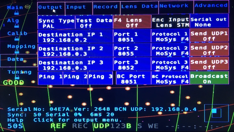
- Sync Type - Select your GenLock Input signal, Black Burst, TriSync and SDI are accepted, but in SD format, HD is NOT SUPPORTED.
- Test Data - Select diferent test patters of data set via network.
- F4 Lens - Turn On if using DigiLens, this option also shows in Lens Data sub menu.
- Encoder Lens Input only shows which lens encoder is selected on Input sub menu.
- Serial Out - Enables MoSys serial output if not using ethernet option.
Unicast
- Destination IP 1, 2, 3 - Set the input to send unicast UDP data.
- Port 1, 2, 3 - Selects the UDP port number.
- Protocol 1, 2, 3 - Select the protocol to be sent to each unicast address.
- Send UDP 1, 2, 3 - Enable/Disable the unicast data output.
- Ping 1, 2, 3 - send a ping to a Destination Address.
Broadcast
- BC Port - Selects the UDP broadcast port number.
- BC Protocol - Select the protocol to be sent to the broadcast address.
- Broadcast - Enable/Disable the broadcast data output.
Input
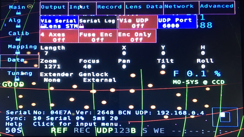
- Via Serial Lens - Select the input mode for lens data (Focus & Zoom).
- STM - External MoSys encoders.
- Serial Log - open a console log window.
- Via UDP - Enable/Disable UDP data input.
- UDP Port - Select the input UDP port.
- 4 Axes -
- Fuse Enc -
- Enc Only -
The screen also display information about
- External encoders X, Y, H, Pan, Tilt & Roll.
- Lens Focus & Zoom encoders.
- GenLock input signal type/status.
Record
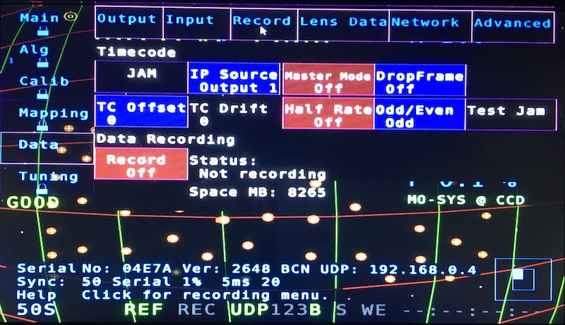
- Jam -
- IP Source Output -
- Master Mode -
- DropFrame -
- TC Offset -
- TC Drift - Display
- Half Rate -
- Odd/Even - Select the field for
- Test Jam -
- Record -
Status information display.
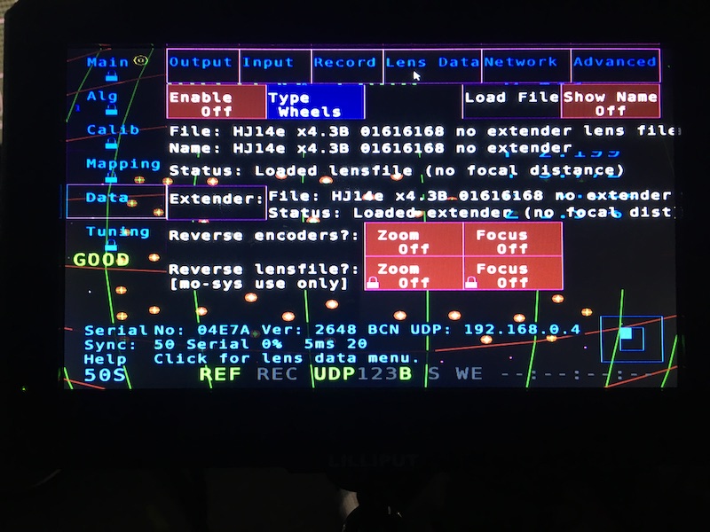
Lens Data
- Enable - Turn On if using DigiLens.
- Type - Select Wheels if using external encoders.
- Load File - Only apply for Digilens.
- Extender - Loads the Extender Menu.
- For external encoders, only set the extender X factor.
- Load Lens file only for DigiLens.
- Reverse Encoders - Invert the encoders direction for Focus or Zoom.
- Reverse Lens File - Invert the encoders direction for DigiLens Focus or Zoom.
Network
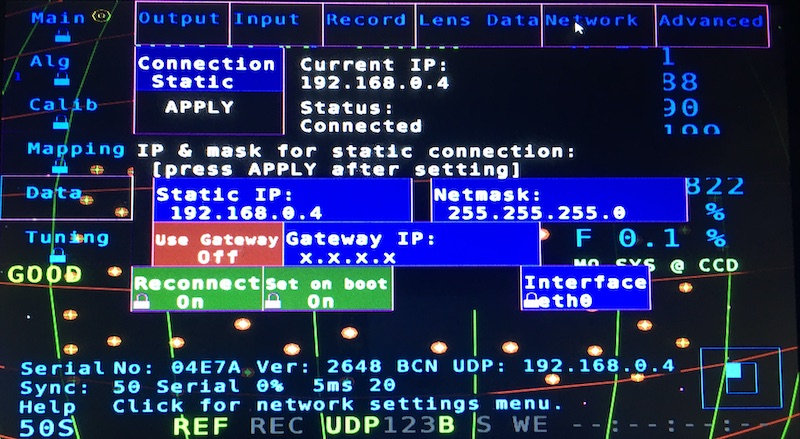
Please reboot after any changes on this menu.
- Connection - Set for Static or Dynamic IP.
- APPLY - Apply settings (you need to reboot unit).
- Static IP - This system IP address.
- Netmask - This system netmask.
- Use Gateway - Enable/Disable gateway address to talk to the Internet.
- Gateway IP - Gateway address for Internet conectivity.
- Reconect -
- Set on boot -
- Interface - Selects the interface to configure on this menu.
- eth0 is the Ethernet port.
- eth64 is the IP camera communications port.
Advanced
- F4 Status - On to send data to D3.
- F4 ST ID - On to be read properly on D3.
- Serial IO - Must be On for Gen Lock and Lens Encoders (reboot needed to apply changes).
- Use IMU - Need to be on, so IR camera works.
